AUTOSAR Run Time Environment
The AUTOSAR architecture as discussed primarily can be broken into three major parts
- Application layer- includes various application specific software components that are designed to execute a set of functions/tasks.
- AUTOSAR Run Time Environment (RTE)- RTE acts as a middle layer between the application layer and the Basic Software. The RTE is responsible for communication between the software components of the application layer ( intra and inter ECU communication) and the communication between the application layer and the Basic Software (BSW).
- Basic Software (BSW)- BSW module is the standardised software module which offers the various services to run the functional part of the upper software layer.
The application layer software modules communicate with each other through the Virtual Function Bus(VFB). From a general perspective, the virtual function bus can be described as a system modeling and communication concept. It is logical entity that specifies how the application modules need to communicate in the AUTOSAR architecture.
The AUTOSAR Runtime Environment (RTE) is the central connecting element in an AUTOSAR ECU architecture. It realizes the interfaces as provided by the VFB ( it actually allocates the memory, specifies the ports etc) in order to enable interaction between the software components.
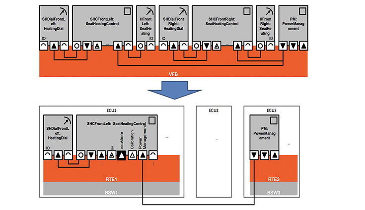
Virtual Function Bus to RTE Mapping
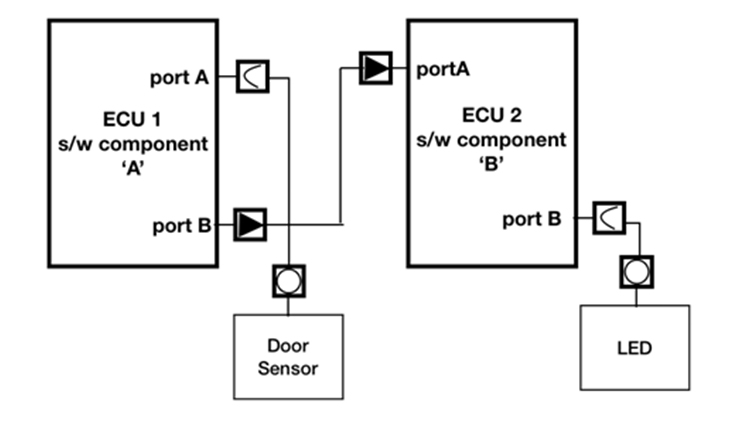
In simple words, realising the Virtual Function Bus in the ECU level is done by the RTE. Lets understand the RTE with an use case by decoding the role of RTE in AUTOSAR architecture using a side door management application. The use case is “if the side is open it has to be indicated to the driver (user) that the side door is open”.
We can do this by building two software components that are distributed in two ECUs. Software component ‘A’ present in ECU 1 will read the signal from the sensor in the door through PORT A . Based on reading the signal from the sensor it will take a decision if the door is opened or closed and send the decision to the software component ‘B’ through PORT B. Software component ‘B’ present in second ECU (ECU2) will receive the signal through port A. The software component ‘B’ will now “Turn ON” (write) the LED if needed to warn the driver through port B.
VFB view
This high level; system design is created using the Virtual function Bus and the xml file will be generated using a tool by the OEM. The xml file will have all the configuration details and serves as a reference document. The OEM will share the xml file (system file) and also define the AUTOSAR standard (say AUTOSAR 4.2) in which the software should be developed. The Tier1 company will load the xml file in his tool and will extract all the system level information. The Tier 1 will now go on to realise the system level file into an actual ECU.
Let’s start discussing on how the RTE is designed and it responsibilities
- The first major work of the RTE is to read the data from the read pin. For this the RTE design must include how many bytes will be transmitted and received from the PIN, what API needs to be called etc.
- The application software is developed with runnables. Runnables is nothing but a small function. Let’s assume that the application software component ‘A’ has three Runnable . The RTE is responsible for executing the runnable in a particular sequence. The RTE will set the sequence , allocate the memory and will make sure that the runnables are executed in the proper sequence.
- Two different software components may be sharing the same memory to save memory. This is also managed by the RTE.
- The OS will be running independently. The OS will trigger the RTE if it wants a task to be executed. The RTE is responsible for executing the task once it receives a trigger from the OS.
- The RTE is also responsible for estimating the time required to complete a task. It will store this time in a memory and produce a duplicate value in a different memory location. It will share the value from the duplicate memory when called upon. This process will not hinder the execution that is carried out currently. Creating a sharable memory is an important responsibility of the RTE.
- The RTE also ensures that the data is received in the correct sequence. The byte order will be maintained to ensure the reliability of the data.
- The application software will communicate with the BSW only through the RTE. However, in exceptional cases where execution speed is very critical the data can be directly accessed by the application software from the BSW.
Now lets get back to our use case
When the READ API is called by the application software component, the RTE will read the value of the sensor from the I/O pin of the micro controller through the BSW. The value of the sensor will be transmitted back to the Application software through a call back function. Logic in the Application software A could have written as if there are two runnables (we assume a logic for easy interpretation). The first runnable will read the sensor value from the RTE and it may calculate how long the door is open. The second runnable in the software component A will take this value from runnable 1 ; it will also fetch calibrated sensor value that is stored in the RTE and check with the value received from runnable 1. If the value exceeds a particular threshold(say 3 seconds) then it may send a signal to the software component B in another ECU to alert the driver that the CAR door is open. This signal will be sent through port B of ECU 1. The RTE will now read the port B and call the communication stack. If the data is a periodic signal then the communication stack will read the data from the buffer periodically. If it’s a trigger based data then the RTE will inform the communication stack whenever there is a trigger. The data in the buffer will be available as Programmable Data Units(PDUs). The communications tack will convert it into CAN frame or FLEXRAY frame based on the configuration and send the data to the second ECU through the interface/bus.
The reverse logic is applied in the second ECU to extract the data and trigger the LED. It may be noted that all the components are running independently. The RTE is responsible for memory management and alignment, data distribution and real time synchronisation.