System Architecture
End-to-end vehicle network topology
Isolated CAN, Standard CAN, CAN FD, and LIN feed into the S32K144 — the ESP32 C3 routes selected signals to cloud, mobile app, reverse channel, and intrusion detection.
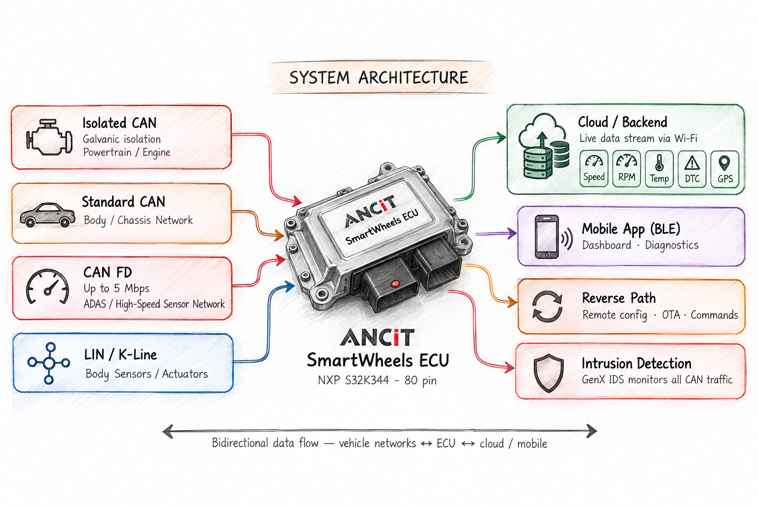
One ECU that bridges your vehicle networks and connects them to the cloud. NXP S32K144 handles 3× CAN + 1× LIN routing with 20 digital inputs, while the onboard ESP32 C3 delivers WiFi and BLE telematics — all configurable via SmartWheels GenX with zero embedded code.
Hardware Specifications
NXP S32K144 (ARM Cortex-M4F, 80 MHz, ASIL-B) with onboard ESP32 C3 — wired vehicle network gateway and wireless telematics in a single 80-pin automotive ECU.
ARM Cortex-M4F @ 80 MHz | ASIL-B | 3× CAN + 1× LIN + WiFi + BLE · 20 DI · Multi-DO · Analog I/O
| CORE | |
| Microcontroller | NXP S32K144 (ARM Cortex-M4F, 80 MHz, 512 KB Flash, 64 KB RAM) |
| Power Supply | 10.8 V – 36 V (Automotive Grade) |
| Operating Temp. | -40°C to +85°C |
| COMMUNICATION INTERFACES | |
| CAN Channels |
|
| LIN | 1× LIN 2.x — Master or Slave configurable. CAN ↔ LIN bridging via GenX, no hand-coding. |
| Wireless |
ESP32 C3 Mini onboard — UART-connected to S32K144. Handles WiFi and BLE stack independently from the main MCU. Configured via the Telematics tab in SmartWheels GenX — define cloud endpoints, CAN signal subscriptions, BLE services, and OTA policy without writing ESP32 firmware.
|
| DIGITAL I/O | |
| Digital Inputs | 20× DI — High-speed configurable for 5 V, 12 V, 32 V, and VBAT signals. With frequency measurement. Switch sensing and speed signals. |
| Digital Outputs |
|
| ANALOG I/O | |
| Analog Inputs | 10× AI — 4× 0–10 V, 4× 0–5 V, 2× 4–20 mA current loop |
| Analog Outputs | 2× AO — 4–20 mA for actuator control and reference signal generation |
| PERIPHERALS & DEBUG | |
| Memory & Debug | 64 Mb external Flash, 4 KB EEPROM, Onboard Segger J-Link Debugger |
| Indicators | Passive Buzzer, RGB LED |
System Architecture
Isolated CAN, Standard CAN, CAN FD, and LIN feed into the S32K144 — the ESP32 C3 routes selected signals to cloud, mobile app, reverse channel, and intrusion detection.
Use Cases
Gateway functions and Telematics functions run simultaneously on the same SmartWheels ECU — configured via GenX, no separate hardware needed.
Forward and filter messages across Isolated CAN, Standard CAN, and CAN FD simultaneously. Per-ID routing rules, ID translation, and signal scaling — no hand-coded routing logic.
Connect LIN body sensors and actuators to the CAN backbone. GenX handles the LIN schedule and frame packing automatically — no LIN stack integration required.
Collect 20 digital and 10 analog inputs and publish them as periodic CAN messages. Reduces wiring complexity in multi-sensor setups — any value also uploadable to cloud.
GenX IDS monitors all 3 CAN buses simultaneously. Unexpected message rates, unknown IDs, or anomalous signal values trigger alerts — logged locally and pushed to cloud via ESP32.
GenX schedules which CAN signals the ESP32 C3 collects and uploads to your cloud endpoint over WiFi — speed, temperature, DTC events, counters. Periodic or event-driven.
Push firmware updates over WiFi to the ECU itself or to any CAN-connected node downstream. No physical programmer access — ideal for fleet and field deployments.
Run UDS diagnostics over WiFi from a laptop or tablet on the workshop floor — replaces wired CAN dongles for routine service checks. No cable runs needed.
Pair with Android or iOS apps via BLE — expose vehicle data, control outputs, or unlock features from a smartphone without any additional radio hardware.
Capture CAN traffic and stream it over WiFi to a local server or cloud endpoint. Useful for vehicle testing, calibration sessions, and post-drive data analytics.
Trigger CAN messages and digital outputs from a WiFi or BLE command — remote lock/unlock, accessory control, or feature flag switching from your backend or mobile app.
Powered by SmartWheels GenX
SmartWheels GenX lets you define CAN routing tables, WiFi cloud endpoints, LIN schedules, IO mappings, and IDS rules visually — generate firmware and flash. No embedded stack integration required for either the gateway or the telematics functions.
Contact us for a quote, datasheet, or to discuss your application. Ships within 2–3 business days.